Tuesday, November 27, 2012

Motion in One Dimension with Air Drag

Purpose: To analyze how changing force affects motion in one dimension.

Introduction Questions:
1) By unit analysis, show that the above equation (Vnew = Vold +aavg*delta(t)) is valid.
m/s = m/s + (m/s^2)*s = m/s

2) Why do we use aavg in equation (1)?
- We assume that acceleration is changing

3) Come up with an analogous equation relating Ynew to Yold.
Ynew = Yold + deltaY

4) What is the benifit of choosing a small delta t?
- For more accuracy

Questions: Fd = -kv (where k is a proportionality constant)

1) Draw a detailed motion diagram of the object falling down.


1a) Now draw a force diagram for the object falling down. Include vectors for all forces, and write a statement of Newton's Second Law. Solve for the acceleration.               Force Diagram
- For every action there is an equal and opposite reaction.
Fnet = Fd - Fg
ma = Fd - Fg
a = (Fd - Fg)/m
a = (-kv - mg)/m
a = (-kv)/m - g

1b) Give the condition for the object at terminal velocity (hit: a = 0). Using the condition solve for k.
0 = (-kv)/m - g
g = -kv/m
mg = -kv
k = -mg/v(terminal)

1c) Substitue k into your expression for the acceleration from part a.
a = -(-gm/v(terminal))v/m - g
a = gv/v(terminal) - g
a = -g(v/v(terminal) +1)

2a) What are the assumptions?
- t = 0 s
- g = 9.8 m/s^2
- v = 100 m/s
- r = 1000 m
- v (terminal) = 40 m/s
- delta t = .1 s

2b) What is v-halfstep?
- Taking the average velocity at two times to find the actual velocity

2c) What is a-halfstep?
- Taking the average acceleration at two times to find the actual acceleration

3) Using the graph paper provided, draw scaled graphs of position vs. time, velocity vs. time, and acceleration vs. time for the object, first assuming no air drag. Make predictions on another sheet of paper about how position and velocity would change if you include air drag.


The position vs. time graph that we predicted is very similar to the actual position vs. time graph. However, the velocity vs. time graph that we predicted is no where near the actual graph. I believe that we accounted for drag wrong and we predicted the graph without drag wrong too.

Now look at a drag force that is dependent on the square of the velocity. Assuming a drag force, Fd = |kv^2|, find the new formula for the acceleration.

Conclusion: This lab was complicated. Even though we did it more as a class, it was still difficult. There could have been a lot of different kinds of error. The fact that most of us didn't really understand it, is cause for a lot of error. I think the only way to do better on this lab is to do it over again.

Friday, October 19, 2012

Centripetal Force

Purpose: To verify Newton's second law of motion for the case of uniform circular motion.

 Table of Trials and Times
The table above shows the five trails for two different masses for the bob. The radius was the same for both masses. To find the time we spun the bob around in a circle 50 times and that gave us our time. The frequency was found by dividing the revolutions (50) buy the time. The time was different for each trial. To find the velocity it is (2pi*50*radius)/time. To find acceleration, it's just velocity/time. To find force we did the (bob mass*velocity^2)/radius.
Once we did that, we found the hanging mass. To find that we hung weight from the bob. The weight was determined by where the weight leveled out the bob to the radius. After found the hanging mass we could find weight, which is just hanging mass*gravity. Then we found the difference between the weight and the force for each trial. As you can tell, for the first bob mass we have under 6% difference for each. Then for the second bob mass, we have under 6.5% difference.

This is the force diagram for the spring. The spring is what the bob is connected to. There are only two forces acting on it. The force of static friction and the force of tension. The forces are equal.


This is the diagram for the hanging weight that held the bob in place at the radius. There are two forces acting on it. The force of tension and the force of gravity. These two forces are equal.


Conclusion: I learned that the hanging weight should be the objective of the force that we found. For sources of error, we could have timed things wrong, measured things wrong, or any other possible human error. To improve we could do more trials and take the best five. When adding mass to the hanging bob, the centripetal force stays the same, but the radius the bob is at changes.

Tuesday, October 9, 2012

Drag Force on a Coffee Filter

Purpose: To study the relationship between air drag forces and the velocity of a falling body.

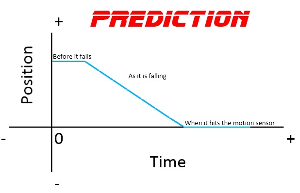
This is the prediction for the position versus time graph. Before the fall, there is a constant position because it is being held in the same place. Once it falls, the coffee filters decrease in position moving to the floor (origin). The once it hits the floor, it stays in the same place because there is nothing causing it to come back up.


These are all of our trials for the different number of coffee filters. We started with nine filters and did five trials. Then from there we took one filter away after five trials with the same number of filters. We ended with one coffee filter.


This is the position versus time graph. This is the best one out of all of our trials. We found the best fit line and our slope was -2.004. The actual would be -2.


This is the curve from out plotted points. The y-axis is the number of coffee filters, and the x-axis is the absolute values of slope averages of the five trials for each value of filters. With the power fit line, the A = k and the B = n in the drag equation we used. Drag = k|v|^n. For our value of n, we have a 2.289. The actual is supposed to be a 2. Our percent error is 14.45%.


The equation for drag moving through a fluid is:
drag = .5*density*v^2*area*drag coefficient 
This is equation is similar to ours where velocity is squared. However, in the fluid equation are is used not surface area. To compare the drag fluid equation to the normal drag equation (drag = 1/4 * Av^2) you can see many more similarities.  

Conclusion: We learned that air slows down the fall of objects. Also, the less mass there is the more the air acts upon it. Our error could be from not dropping from the exact same height each time. Not dropping it at the same height does affect the experiment. The higher we drop the coffee filter, the longer it takes to reach the ground. If we had dropped the filters from the exact same height each time, then we would have better numbers. Next time, we can make sure we drop the filters at the exact same height and even do more trials to have more data.


Tuesday, September 25, 2012

Working With Spreadsheets

Purpose: To get familiar with electronic spreadsheets by using them in some simple applications.


These are pictures of the first spreadsheet we did. We used f(x)=Asin(Bx+C) as our function. We had x start at zero and then go to 10 by 0.1. In the equation, A = amplitude which is 5 in this equation, B = frequency which is 3, and C = phase which is pi/3.
The first picture has the equation shown. In the second picture, we have the numerical value after excel plugged in the numbers.


This is the graph of the plotted points. The x values are that of which we used in excel sheet. It starts at zero and goes to ten by 0.1. The y values are the numerical values we got after excel plugged the numbers into the equation.
The original equation is f(x)=5sin(3x+(pi/3). After doing the best fit quadratic line, out equation comes out to be f(x)=5sin(3x+1.05). This is fairly correct when pi/3 is rounded to two decimal places. We used 1.047198 for pi/3.


These are the excel spreadsheets from the second equation we did, f(x)=A+Bx+Cx^2. In this equation, A is position (x0) which equals 1000m. B is velocity (v0) which equals 50m/s. Lastly, C is gravity which equals -4.9m/s^2. For the x values, x is represented by delta t which equals 0.2. We interpreted this as the x values start at 0.2 and increase by 0.2 as well. We had it go to ten just like the last equation.
The first spreadsheet shows the equation and the second spreadsheet shows the numerical value after excel plugged the numbers into the equation.


This it the graph that comes from the second equation. The x values are delta t which starts at 0.2 and increase by 0.2. The y values are the numerical values given by plugging the numbers into the equation.
Our original equation was f(x)=1000+50x-4.9x^2. The best fit line we got was f(x)=1000+50x-4.9x^2. The equation is the exact same as the one we used.


Conclusion: This was a good lab to do because we were able to practice or learn how to use excel. It was also good because we could see how the different parts of equations affect the graph. In our group we originally had put acceleration (gravity) as positive 4.9m/s^2. Our graph was completely different from the one that was negative. Our parabola was upside down opening up. That was the only problem we had in this lab. Once we fixed the problem, it all made sense.

Tuesday, September 18, 2012

Vector Addition of Forces

Purpose: To study vector addition by: 1) Graphical means and 2) Using components. A circular force table is used to check results

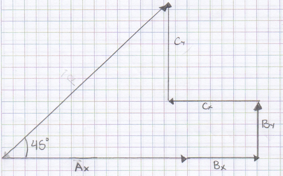
Our group started with magnitudes 200cm, 100cm, and 150 cm with degrees of 0, 41, and 132 respectively. This is the graph of the vectors given. Thee scale is 1 cm = 20 g.
Vector D is the resultant force. The angle of vector D and the x-axis is 45 degrees.
This graph also shows the x and y components of each vector.


Vector A) Ax = 200g                                       x = 200+100cos(41)+150cos(132) = 175.1g
                Ay = 0g                                            y = 0+100sin(41)+sin(132) = 177.1g
Vector B) Bx = 100cos(41) = 75.5g
                By = 100sin(41) = 65.6g                 R = 250g at 45 degree
Vector C) Cx = 150cos(132) = -100.4g          Rx = 250cos(45) = 176.8g
                Cy = 150sin(132) = 111.5g             Ry = 250sin(45) = 176.8g
 
This graph is solely the x and y components of each vector. The final vector goes from the tail of the first to the head of the last. That vector is the resultant vector.
These pictures are of the circular force table. Our measurements were correct because the first time we put the weights on at the given angles, it was balanced.

This is the picture from the simulation website. using our vectors, we got the same resultant vector.


Conclusion: In this lab we worked with vectors. We found the resultant vector from three vectors given. With this we found that it is balanced with wights and angles that were given. I learned that vectors are basically trig problems. This problem was fairly simple and we didn't have any errors with calculations. We did calculate our vectors two ways, mathematically and with a graphical approach. In our math we got whole numbers but graphically we got numbers that were decimals but could be rounded to the same numbers as ours. Another source of error comes from using the force table. There could have been friction or it could have been unbalanced (in out favor) which would have thrown off the balance. If out calculations were off and the table wasn't balanced but it said it was is why it would be in our favor.

Tuesday, September 11, 2012

Acceleration of Gravity on an Inclined Plane

Procedure: 1) To find the acceleration of gravity by studying the motion of a cart on an incline. 2) To gain further experience using the computer for data collection and analysis.


Ramp 1 1.65 degree
This is the first ramp (not drawn to scale). The length of the long leg is 228.2 cm. To find the height (short leg), we took the height from the ramp on either side and then subtracted them. From there we went to find the angle of elevation. We took arc tan(6.2/228.2) and this came out to theta = 1.56 degrees.
Ramp 2 3.6 degree

This is the second ramp (not drawn to scale). This one had larger angle of elevation. We did the same thing to both sides of the ramp to find the height and it came out to be 14.3 cm. Then we took arc tan(14.3/228.2). Theta = 3.6 degrees.
Graph 1

This is the position verses time graph. It is a parabola because the car went up the ramp and then back down. The car went up the ramp where the velocity was decreasing, and then the car went back down the ramp where the velocity increased.
Graph 2

This is the velocity verses time graph. For this line, there are two different accelerations. This is because there are two different events happening, the car increasing in velocity and the car decreasing in velocity. It is linear because it shows the slope of the parabola from the position verses time graph.


Table 1.56 degree

Trial for 1.56 degree incline a1 (motion up) m/s2 a2 (motion down) m/s2 Gexp m/s2 % difference
1 0.33 0.18 9.4 4.10%
2 0.36 0.18 9.9 1.00%
3 0.34 0.19 9.7 1.00%
This table shows the acceleration for the incline of 1.56 degrees. Both the acceleration for the car moving up and down are on there. By using the equation Gexp=arc sin((a1+a2)/2) we get experimental gravity. Also, we got the percent difference between them and gravity (9.8). For example, Gexp=arc sin((.33+.18)/2)=9.4 for trial one.

Table 3.6 degree

Trial for 3.6 degree incline a1 (motion up) m/s2 a2 (motion down) m/s2 Gexp m/s2 % difference
1 0.69 0.5 9.5 3.30%
2 0.69 0.54 9.8 0.00%
3 0.72 0.52 9.9 1.00%
Conclusion: This table shows the acceleration for the incline of 3.6 degrees. Both the acceleration for the car moving up and down are on there. By using the equation Gexp=arc sin((a1+a2)/2) we get experimental gravity. Also, we got the percent difference between them and gravity (9.8). For trial two, we get a zero percent difference. A source of error would be that we didn't calculate the angle, height, or length of the ramp correctly. We could have done more trials to get even better results.

Tuesday, September 4, 2012

Acceleration of Gravity

Purpose: 1) To determine the acceleration of gravity for a freely falling object. 2) To gain experience using the computer as a data collector.

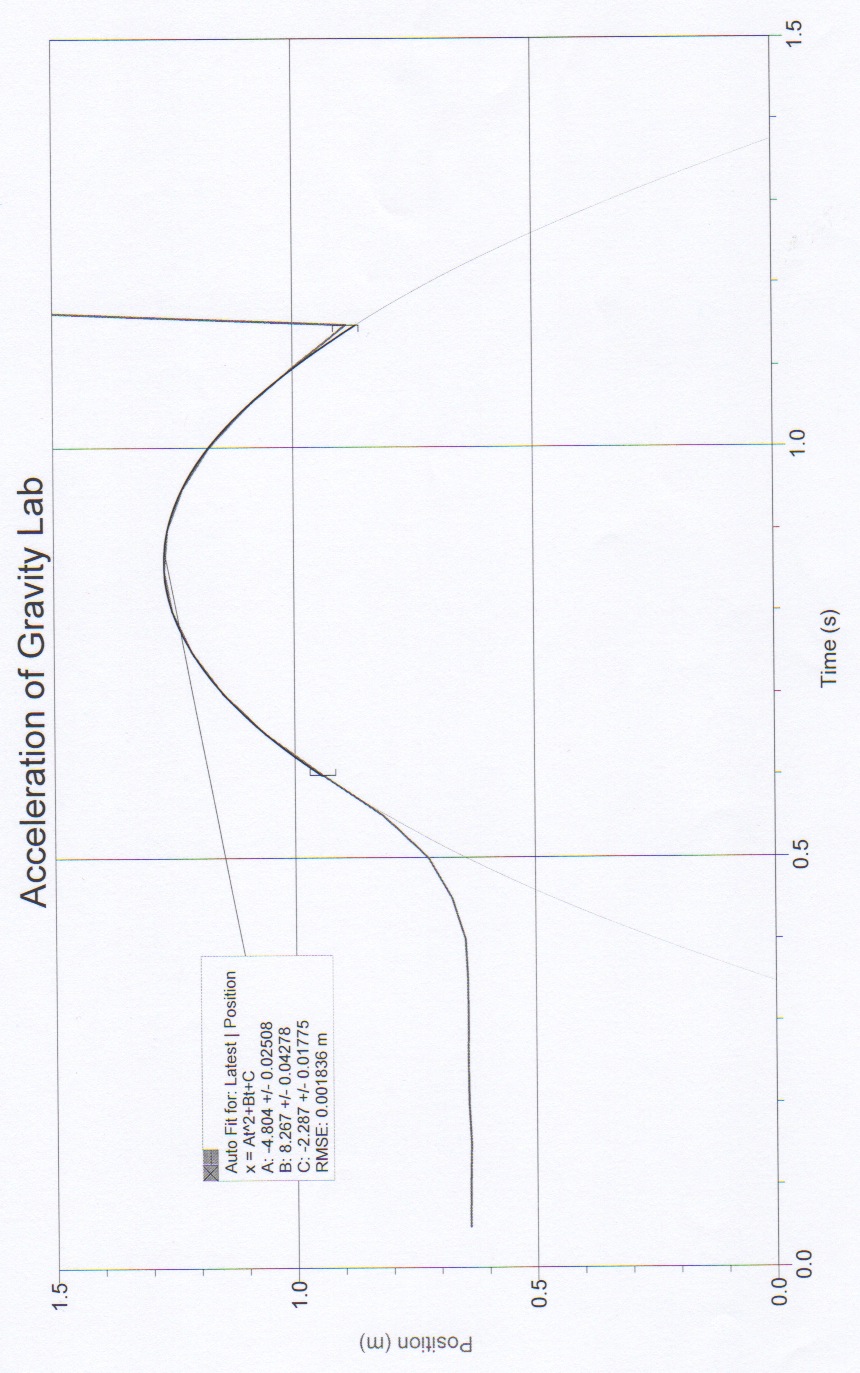
 We had to throw a ball up over the motion detector to get a position verses time graph. We were supposed to get a parabola for the path of the ball, like we did. The reason it should be a parabola is because the ball will go up and then at some point come down.

Also on this graph is the best fit line. This line shows the closest equation for a parabola. This parabola is a good example because it is almost half of gravity, 9.8 m/s/s, at 4.8 m/s.

This graph is velocity verses time. This graph is a straight line because it takes the slope of the position verses time graph which is linear. The best fit line is also there. This line is a little under what gravity really is. The slope of this line is 9.1 m/s/s.

The slope of this graph is negative because the parabola of the position verses time graph is negative. That is negative because the ball went up and then down. Since the slope of this line is the slope of the parabola the slope has to be negative.


Trial    gexp (2a) (m/s/s)    % difference       gexp (m) (m/s/s)     % difference
1 9.608 1.96 9.13 6.84
2 9.462 3.45 9.259 2.97
3 9.524 2.82 9.416 3.92
4 9.634 1.7 9.613 1.91
5 9.586 2.18 9.74 0.61
This table shows five different ball drops. For each trial we took double the velocity to see how close it is to gravity. The percent difference shows the difference between what we got and what gravity really is. Then we took the slope of acceleration to see how close to gravity it is. The percent difference show the difference between gravity and the slope that we got.

This is the motion diagram we made for position verses time. We labeled the origin and the positive direction. Also, we showed the direction of acceleration. Where the purple arrow is, it shouldn't say a=0, it should say v=0. On the left side it shows that the ball is decreasing in motion in the positive direction. On the right side, the ball is moving in the negative direction and is increasing. The point where there is a break in the motion diagram connected by the pink doted line is where v=0 because there is the point where the ball begins its dissension.


In this lab we found the velocity and acceleration from the path of a ball being tossed in the air. With those we found the difference in what we found and what is actual. Nothing was perfect, because a ball thrown by a person can not be a perfect parabola. That is why we did more than one trial so that we can  get as close to perfect as possible. For all of the velocity, the differences were less than four percent. However, over all the difference for acceleration beat velocity except for one trial. Trials 2-5 were all less than four percent as well. The first trial was less than seven percent. Trial five for acceleration was less than one percent leaving it to be the best over all.